









New Plasco
Project Outline
The design of the New Plasco Tower was initiated in response to the needs of the owners and tenants who lost their workplaces in the fire. The construction of the tower in central Tehran provides an opportunity to reconsider the historic and green surroundings and the way the building engages in dialogue with them, the former Plasco Building and its characteristics, the fire incident and the sacrifice of the firefighters, and ultimately the concept of the high-rise building and its relationship with the city.
Design Criteria
Context (Gardens):
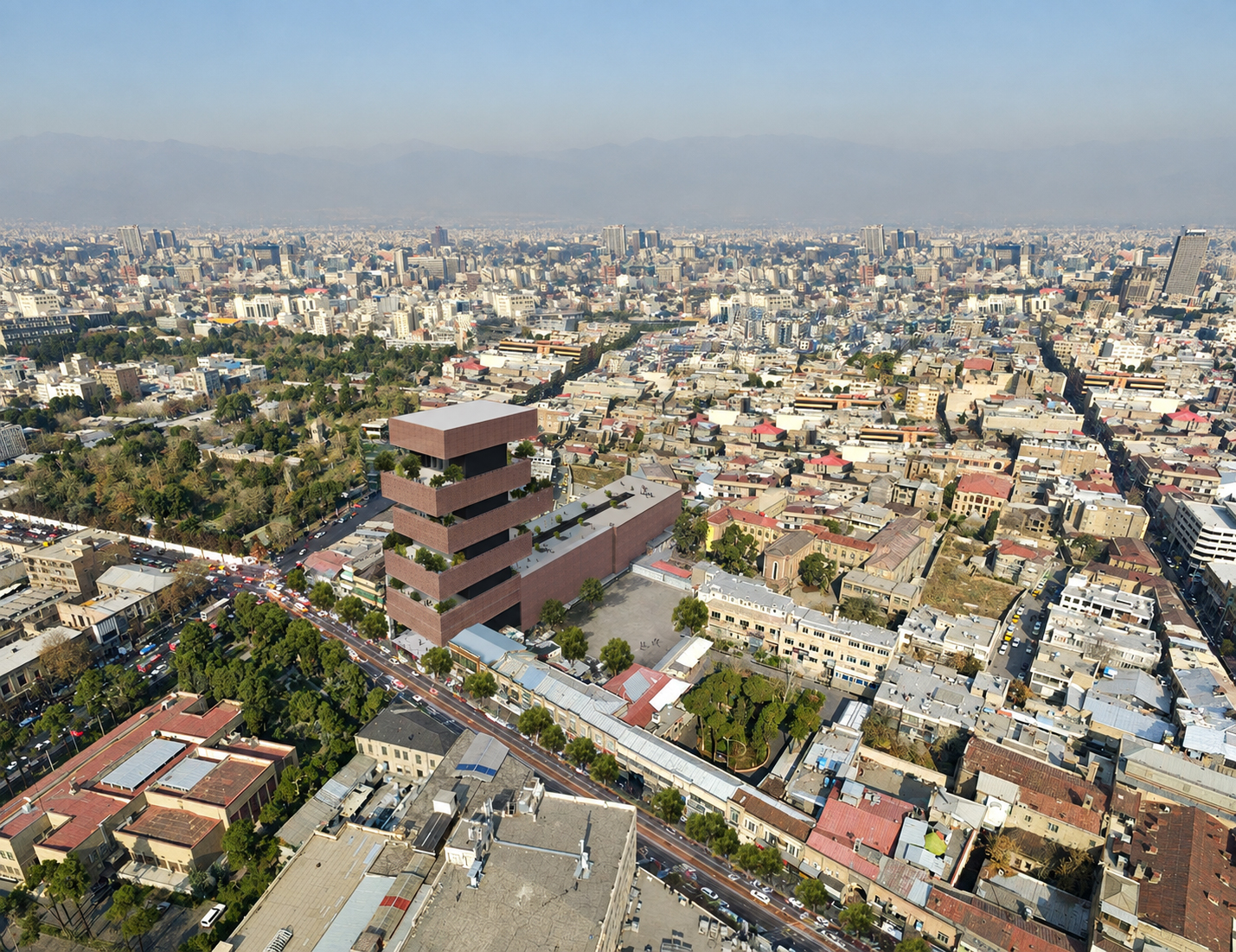
The gardens of the British, Russian, Turkish, and German embassies form a collection of valuable historic green spaces in central Tehran. Although they are accessible to the public, they create a visually pleasant environment and valuable views, providing an appropriate opportunity for interaction with the New Plasco Tower
Pirnia Neighborhood:
The Pirnia neighborhood, with its valuable architecture from the early modern period in Iran, represents a combination of elements of historic architecture with the early modern architectural structure of Iran, evident in buildings such as Jandark School and Pirnia House. The existing relationship between solids and voids within this urban fabric creates a valuable structure with the potential to be extended into the vertical structure of the New Plasco Tower.
Former Plasco Tower:
The former 16-storey Plasco Building was the first high-rise tower of Iran’s modern era. Conceived as a simple vertical box placed on the ground, the tower incorporated a structural system that was advanced and unprecedented in Iran at the time and was comparable to contemporary architecture worldwide. During its 54-year lifespan, the tower played an important role in the collective memory of Tehran’s citizens and visitors from other cities in Iran.
The defining characteristic of the former Plasco Building as Tehran’s tallest tower can no longer be repeated. Therefore, emphasizing the vertical axis would not represent a new achievement for the New Plasco project. In contrast, the horizontal axis provides different possibilities for the spatial organization of a high-rise building and its relationship with the city. The New Plasco is therefore conceived as a tower with an emphasis on the horizontal axis.
Firefighters’ Memorial:
Commemorating the memory of the 16 fallen firefighters who heroically rushed to save people is integrated into the New Plasco Tower and occupies a dedicated space within the most significant part of the project.
Relationship with the City:
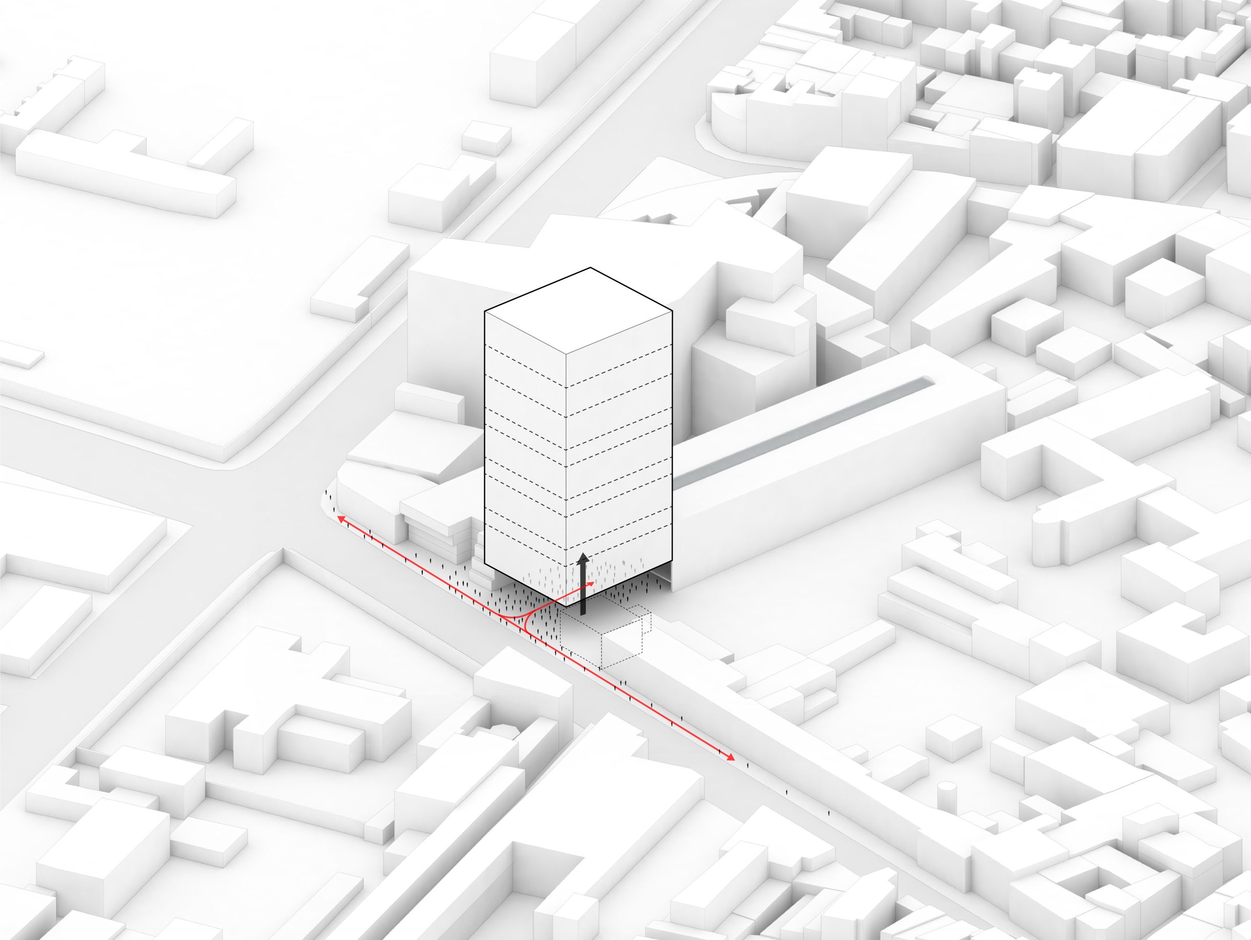
The New Plasco Tower is intended to pay particular attention to the city and the creation of urban space. In return for occupying the skyline, it gives its ground level back to the city, creating a space that accommodates the flow of environmental forces and acts as an interface between the city and the tower.
Architectural Concept
In this design, the main volume of the tower is lifted above the ground, creating a large open space at ground level. Conceived as an urban iwan, this space attracts visitors toward the commercial areas while also functioning as a place for pause and gathering.
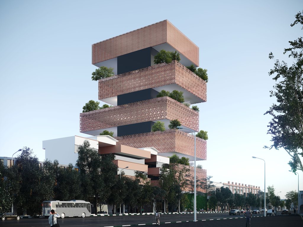
The main body of the tower is divided into five principal horizontal volumes, with four voids situated between them. These four voids are conceived as four gardens, each dedicated to a public activity. The first garden, located at the same level as the roof of the northern Plasco Building, contains hospitality spaces including a café, restaurant, and green space. The second garden is dedicated to the Museum of Old Tehran, the third to the Plasco Museum, and the fourth to the Firefighters’ Museum and Memorial.

The main volumes of the project, containing commercial and service functions, are positioned as floating volumes of varying dimensions. These volumes are connected by two main concrete cores containing circulation and other service spaces.
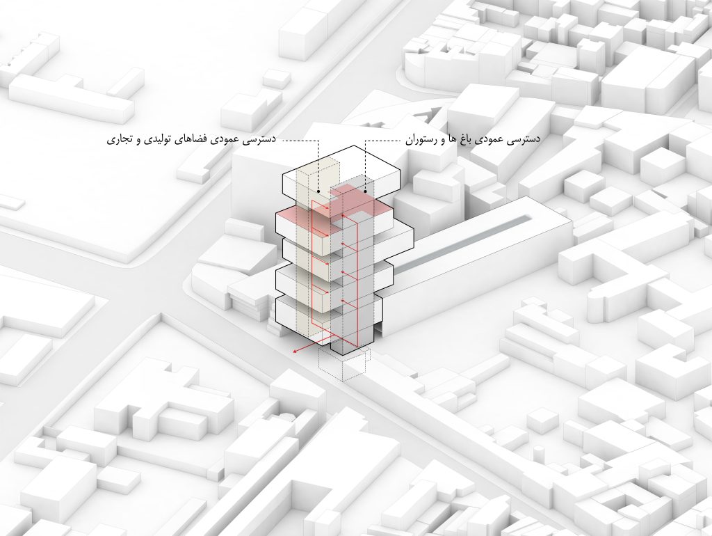
In the spatial organization of the project, the fifth basement level contains storage and mechanical facilities, while basement levels one to four accommodate shops. The ground floor is conceived as an urban plaza; the first and second floors contain shops, the third through thirteenth floors accommodate commercial spaces, and the fourteenth floor is dedicated to a restaurant.

Memorial to the 16 Firefighters
The Firefighters’ Museum Garden is the highest garden in the New Plasco building. Sixteen vertical columns occupy the central space of the garden, extending through openings cut into the floor and ceiling. These columns are intersected by a floating spatial layer, revealing a void that evokes a sense of absence. The voids between the columns are recreated through light, with each one dedicated to one of the firefighters.
Façade
Two materials are used for the cladding of the project’s main façades:
- Dark, matte stainless-steel sheets for the vertical cores.
- Hollow brick for horizontal floating volumes
Four different designs inspired by the brick patterns of ancient Iranian architecture have been used for the brick coverings. These patterns complement one another and express the concept of unity in multiplicity.
Structural System
The structure of the New Plasco building consists of two parts: A five-level basement structure with a height of 27 meters and a 15-story above-ground structure with a height of 78.6 meters.
Five Basement Floors:
The gravity-load-resisting system of the basement structure is a column–slab system. This system eliminates the need for primary and secondary beams, allowing loads to be transferred directly from the floor slabs to the columns and then to the foundation. For the floor system, waffle slabs can be used instead of solid concrete slabs. In addition to reducing the equivalent thickness of the floor slabs, waffle slabs provide greater strength and stiffness and enhance the aesthetic quality of the ceilings.
Regarding the lateral-load-resisting system of the basement levels, it should be noted that the retaining walls surrounding the entire basement structure, together with the fact that these levels are buried in the soil, give the basement structure significantly greater stiffness—approximately ten times that of the above-ground structure. Consequently, the basement structure effectively acts as a support for the superstructure. Therefore, the dynamic support level of the structure can be considered to be at the first-floor level (Zero level), meaning that the basement structure is not subjected to seismic loads.
15 Above-Ground Floors:
The 15-story above-ground structure consists of 5 two-story substructures and 5 floors with an enclosed area between two shear-wall cores. The two shear-wall cores extend through all levels of the structure, from the foundation to roof level. Each is designed as a closed rectangular enclosure measuring 18 meters by 7.7 meters, positioned along the eastern and western sides of the structure. Between every two-story substructure, there is one floor comprising the area enclosed between the two shear-wall cores. The height of each story in the two-story structures above ground ranges from 4.5 to 6 meters. The story heights within the area enclosed by the two shear-wall cores are 4.5 and 8 meters.
Given the irregularity of the plan geometry across the above-ground floors, and the fact that once every two floors is effectively limited to the area enclosed between the two shear-wall cores, the use of a moment-resisting frame system in combination with shear walls is not feasible. On floors where the structural floor area is confined to the space between the two shear-wall cores, it is effectively impossible to position columns in the remaining areas. Consequently, the discontinuity of the columns at these levels makes it impossible to use a moment-resisting frame as part of the lateral-load-resisting system.
Nevertheless, according to Clause 3-3-5-4 of the fourth edition of Standard 2800, buildings exceeding 15 stories or 50 meters in height must employ either a special moment-resisting frame system or a dual system. Such buildings cannot rely exclusively on shear walls to resist all seismic lateral forces. Although the New Plasco structure, with a height of 79 meters above ground level, is required to employ a dual system under this provision of Standard 2800, it should be noted that its lateral-load-resisting system does not consist of conventional concrete or steel shear walls. Instead, it employs composite shear walls comprising two steel plates with a concrete wall between them. In addition to their four perimeter walls, each of the two composites shear-wall cores also incorporates intermediate transverse walls (walls parallel to the shorter direction of the core). Undoubtedly, the use of today’s technology, in the form of a composite shear-wall lateral-load-resisting system, in the new Plasco building can have a twofold impact on the value and appeal of the structure.
The gravity-load-resisting system of the above-ground structure consists of simple frames composed of horizontal beams and columns extending over two stories. For the floor slabs, either steel decking combined with a thin concrete slab or waffle slabs, similar to those used in the basement levels, can be employed. In some frame bays, particularly the outermost bays within the 10- to 20-meter-long cantilevers on the northern side of the structure, rigid beam-to-column connections combined with diagonal or inclined bracing are used to control vertical deflections caused by gravity loads
Furthermore, to ensure more reliable control of vertical deflections caused by gravity loads and dynamic response of the floor slabs, four rows of moment-resisting frames with rigid connections, combined with vertical cross-bracing, have been incorporated along the longitudinal direction of the structure, aligned with the two longitudinal sides of the composite shear-wall cores. To prevent excessively high force demands at the connections between the four moment-resisting frames and the composite shear walls, the upper and lower beams of the moment-resisting frames are not interrupted at their connections to the walls. Instead, they extend continuously along the entire length of the walls to the southern end of the structure. This system eliminates concerns regarding localized damage and failure at the connections between the upper and lower components of the gravity-load-resisting moment frames and the composite shear walls.